Ecosoft INOX MO9 8" reverse osmosis system with Siemens controller

- New

- New
Ecosoft INOX MO9 8" reverse osmosis system with Siemens controller in UK
- Provides 9–12 m³/h flow rate
- Siemens S7-1200 controller for automated operation
- SIMATIC HMI KTP700 Basic touchscreen operator panel
- Stainless steel frame and membrane rack
- Grundfos pump supports stable flow
- Pump frequency control for consistent operation
Product information
Ecosoft INOX MO9 8″ reverse osmosis system with Siemens controller is a high-capacity water treatment system designed for facilities that require a stable supply of purified water. With a production capacity of 9–12 m³/h, the system is suitable for large-scale applications such as utility water treatment, desalination projects, and steam boiler feed water preparation.
The system uses nine 8″ membrane elements and a 7.5 kW Grundfos high-pressure pump to maintain stable performance and up to 75% recovery. It can treat feed water with total dissolved solids up to 4500 mg/L. The Siemens S7-1200 automation platform monitors key operating parameters, including differential pressure, permeate temperature, flow rate, and conductivity.
Pump frequency control supports smooth start-up, helps reduce hydraulic shocks, and lowers mechanical stress on system components. The MO9 system can be integrated into Building Engineering Management systems, allowing operators to monitor performance data and manage the unit as part of a larger water treatment process.


Technical information
Before starting the reverse osmosis system, prepare the membrane, refill the elements, adjust the devices, and perform other system checks.
Avoid major pressure or flow surges inside the spiral-wound elements during start-up, shutdown, or cleaning. This helps reduce the risk of membrane damage. During start-up, gradually switch the system from standstill to operating mode by following these steps:
- Gradually increase the feed water pressure over 30–60 seconds.
- Gradually bring the flows to the operating rate over 15–20 seconds.
- Discharge the permeate obtained during the first hour of operation.
After initial soaking, always keep the elements wet.
To prevent biofouling during long operating breaks, submerge the membrane elements in a preservative solution.
The maximum pressure drop across the full housing length is 2.1 bar.
⚠️Use sterile rubber gloves when working with membrane elements.
⚠️If high microbiological purity is required, disinfect the reverse osmosis system and the permeate tank before installing the membrane.
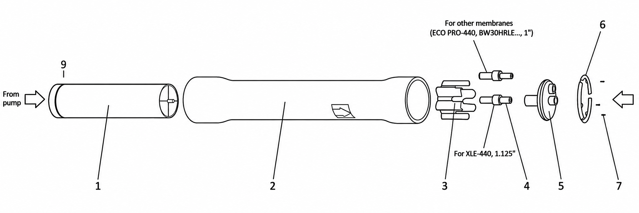
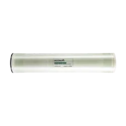
Remove the membrane element(s) 1 from the factory packaging and install it in the membrane housing(s) 2. The membrane element must be installed by removing the end cap. The membrane element must be installed in the membrane housing with the O-ring facing the membrane housing inlet connection, as shown in the figure. The O-ring must be in the opposite direction from the arrow.
After installing the membrane element, install the end cap 5 and secure it to the membrane housing with locking kit segments 6 and screws 7. The screws are unscrewed with an 8 mm hex key.
On the other side of the membrane holder, install the thrust ring 3, as shown in Figure 5.2, then install the adapter 4. After that, install the end cap 5 and secure it to the housing with locking kit segments 6 and screws 7.
Connect the water supply, concentrate, and permeate discharge pipelines to the membrane housing. Secure the housing to the reverse osmosis system frame.
When the system is first started, the first portion of permeate must be discharged into the sewer. The minimum discharge time is 30 minutes.
💡When installing the membrane, pay attention to the direction of the arrow on the membrane holder.
💡If necessary, use glycerin as a lubricant.
Consumables
-
£ 14.40 excl. VAT£ 17.28 incl. VAT
-
£ 1,795.71 excl. VAT£ 2,154.85 incl. VAT
-
£ 1,613.98 excl. VAT£ 1,936.77 incl. VAT
-
£ 1,939.91 excl. VAT£ 2,327.89 incl. VAT
-
£ 1,720.51 excl. VAT£ 2,064.61 incl. VAT
-
£ 766.67 excl. VAT£ 920.00 incl. VAT
-
£ 766.67 excl. VAT£ 920.00 incl. VAT


FAQ
-
Why might the Ecosoft MO9TISIEM be suitable for my purposes?
The Ecosoft MO9TISIEM is a high-capacity industrial-grade reverse osmosis system designed for reliable purified water production. It combines efficient performance, digital control, and durable stainless steel construction.
The system can be integrated into a plant-wide upper-level network for monitoring and control of technological processes via SCADA or BMS.
-
What is the difference between the Siemens S7-1200 and Ecosoft OC5000 or OC6000 controllers?
The Siemens S7-1200 supports robust networking through integrated PROFINET, making it suitable for integration into factory-wide SCADA systems and advanced remote monitoring. Its modular design allows operators to add specialized I/O modules or communication processors when needed.
Systems with the Siemens controller also include more instrumentation, such as feed water and permeate conductivity probes, electronic pressure gauges, electronic flow meters, and electronic temperature sensors. Native integration with high-resolution HMI touchscreens allows membrane data to be displayed in real time and gives the operator more detailed process control.
Both controller types can perform standard reverse osmosis tasks. The Siemens PLC is better suited for industrial projects where integration, flexibility, and advanced monitoring are important. The OC5000 and OC6000 controllers are a more compact and cost-effective solution for standard water treatment systems where plant-wide network integration is not required.
-
What additional instruments are available on models with a Siemens controller?
Models with a Siemens controller include several additional instruments. The feed water conductivity cell, CE-01 on the piping and instrumentation diagram, and the permeate conductivity cell, CE-02, continuously measure dissolved solids to help monitor water quality.
Hydraulic performance is monitored by two electronic flow sensors, EFI-01 and EFI-02, located on the permeate and concentrate lines. The system is also equipped with electronic pressure transmitters, EPI-01 to EPI-04, which monitor pressure before and after the sediment filters, at the inlet of the membrane vessels, and on the concentrate line.
An electronic temperature sensor, ET-01, is installed on the permeate line and provides data on permeate temperature.
-
What are the functions of pressure sensors before and after the sediment filter?
The pressure sensors before and after the sediment filter are used to monitor pressure drop. As sand, rust, scale, and other particles accumulate, filter resistance increases. The inlet pressure stays similar, while the outlet pressure drops.
If the pressure drop across the sediment filter rises to 0.6–0.8 bar, the filter should be replaced. If the pressure after the sediment filter drops below 2 bar, the low-pressure switch activates and the system enters fault mode.
If the low-pressure switch is faulty or disabled, the pump may not receive enough water. Pressure below 2 bar can cause cavitation. No pressure may cause dry running, which can damage the pump’s internal components within minutes. If the differential pressure suddenly drops to zero while flow remains high, this may indicate mechanical damage to the filter and it should be replaced.
-
What is the purpose of the pressure sensor after the pump and before the membrane housing?
The pressure sensor located between the pump and the membrane housing is the main instrument for monitoring the operating pressure applied to the membrane. This sensor operates within a 0–16 bar range.
The required pressure can be set on the variable frequency drive. When the sensor reads the set value, the variable frequency drive controls the pump speed to maintain the required pressure.
-
Why is there a high-pressure sensor after the membrane housings?
The high-pressure sensor installed after the membrane housings is located on the concentrate line. It monitors hydraulic resistance inside the membrane elements and supports safe operation of the filtration process.
The sensor before the membrane shows the pressure applied to the system. The sensor after the membrane shows the residual pressure of the reject water before it passes through the concentrate control valve. Using both readings, the Siemens S7-1200 controller can display the differential pressure across the membrane stack.
Differential pressure is one of the key indicators of scaling or fouling. If the pressure drop between the inlet and outlet increases by 10–15%, this may indicate that the feed spacers inside the membrane are becoming clogged with mineral deposits or biological matter, and the operator can decide whether chemical cleaning is required.
-
Where are the conductivity cells located, and what is their purpose?
There are two conductivity cells: CE-01 on the feed water line and CE-02 on the permeate line, as shown on the piping and instrumentation diagram.
The feed water conductivity cell measures the electrical conductivity of the incoming water and provides a baseline for the total dissolved solids entering the system. The permeate conductivity cell measures permeate quality and helps confirm that the reverse osmosis process is removing salts effectively.
An increase in permeate conductivity at CE-02 may indicate membrane damage, scaling, or the need for chemical cleaning. CE-01 and CE-02 usually operate within a similar range of 0–2000 mg/L. If required, the sensors can be changed to match specific process needs. For example, a sensor with a range up to 4000 mg/L can be installed at the feed water inlet, while a more sensitive sensor up to 200 mg/L can be used at the permeate outlet.
-
Where are the flow indicators located, and why are they needed?
There are two electronic flow indicators: EFI-01 on the permeate line and EFI-02 on the concentrate line, as shown on the piping and instrumentation diagram.
EFI-01 measures the volume of purified water produced by the membranes. EFI-02 monitors the volume of concentrate discharged to drain. Together, these readings help the operator evaluate the hydraulic balance and efficiency of the system.
The controller displays this data on the screen. By analyzing the flow readings, the operator can detect changes in system performance. For example, a decrease in permeate flow at EFI-01 may indicate membrane fouling.
-
Is there a 4–20 mA analog level sensor in the system?
The analog 4–20 mA level sensor is not included in the standard package. However, it can be installed in the permeate collection tank as a monitoring device for the Siemens S7-1200 controller.
Unlike a simple float switch that provides only on/off signals, an analog level sensor gives the operator continuous data on the exact water level and available volume in the tank.
-
What is the advantage of pump frequency control in this model range?
Frequency control of the high-pressure pump provides several technical and operational benefits. It helps the system maintain stable pressure or permeate flow under changing operating conditions, such as feed water temperature changes or gradual membrane fouling.
In a standard system, the pump runs at full capacity. With a variable frequency drive, the pump operates only as fast as needed to meet the current pressure demand. This can reduce energy consumption, lower operating costs, and reduce mechanical stress on system components.
The customer also benefits from quieter operation, more stable water quality, and improved equipment durability.
-
Why is there a water temperature sensor on the permeate line?
The water temperature sensor on the permeate line is important because membrane permeability changes with temperature. When water becomes colder, higher pressure may be required to maintain the same flow.
When the operator compares temperature data with pressure and flow readings, it becomes easier to understand whether lower output is caused by seasonal water cooling or membrane fouling. This helps the operator make better manual adjustments to operating pressure and valve positions to maintain stable production.
-
What protocol is used for data exchange in this model range?
Data exchange in this system is primarily based on the PROFINET protocol. This industrial standard enables communication between the Siemens S7-1200 controller and the Siemens KTP700 Basic HMI panel.
The system is also designed for high-level integration into Building Engineering Management through SCADA or BMS systems. This supports remote monitoring and control across several operating levels.
Pressure, temperature, conductivity, and flow sensors transmit real-time data to the controller through analog and digital inputs. The Ethernet-based PROFINET interface synchronizes key parameters, such as pump discharge pressure, flow rates, and TDS levels, between the local HMI and connected supervisory systems.
-
How can the system be controlled from SCADA?
The operator can manage the unit from a remote workstation. The system can be stopped remotely in an emergency or restarted if a software-based fault occurs.
The SCADA system also provides real-time visualization of sensor data, including pressure, temperature, and conductivity. This allows comprehensive remote monitoring without the need to be physically present at the unit. Remote access supports faster response to alarms and reduces the need for on-site intervention during routine operation.
-
What can be displayed on the SIMATIC HMI KTP700 Basic control panel?
The Siemens SIMATIC HMI KTP700 Basic panel is a centralized touchscreen interface that displays real-time operating data and system controls.
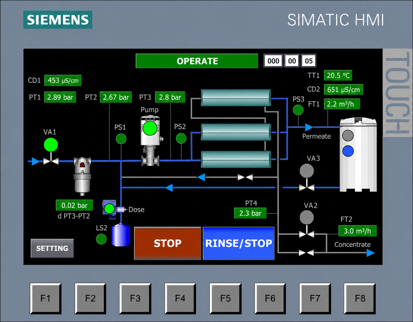
On the main OPERATE screen, the operator can monitor the current operating mode, such as service, stop, alarm, or standby. The panel also displays key hydraulic parameters, including permeate and concentrate flow rates, permeate temperature, and TDS levels for both feed water and permeate.
The display shows the pressure profile of the unit, including feed pressure, pressure after the sediment filters, pump discharge pressure, and pressure after the membranes. If an analog 4–20 mA level sensor is connected, the HMI can show the permeate tank level. If a float switch is connected, the controller can display whether the tank is full. The controller can also show a low antiscalant level.
In addition to monitoring, the panel allows the operator to control motorized valves for feed water, forward flushing, and permeate flushing. It can also display three alarm modes. These elements are combined in one dashboard for local system management and fast diagnostics.
-
Why does this system cost more than other models?
The higher cost of this system compared with other models is mainly due to the use of industrial components, including the Siemens S7-1200 controller and pump frequency control.
Although the initial investment is higher, the frequency inverter can reduce operating costs by adjusting pump power consumption to actual demand and water temperature. This helps avoid unnecessary energy use.
The Siemens controller provides precise monitoring of technical parameters, allowing the operator to maintain the correct hydraulic balance and reduce mechanical stress that can shorten membrane life. Over time, service costs can be reduced because detailed monitoring helps identify fouling early and supports timely chemical cleaning before membrane replacement becomes necessary.
Related products


No reviews yet
Be the first to share your opinion!


